Structural principle of torque self-test inner curve hydraulic motor
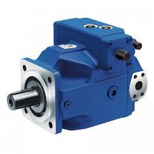
In order to improve the torque measurement level of the internal curve hydraulic motor, based on the comprehensive analysis of the existing torque measurement technology, the structural principle of the torque self-test internal curve hydraulic motor is proposed, and the structural characteristics of the hydraulic motor and the composition of the torque measurement system are analyzed. The piezoelectric ceramic force sensor is used to measure the torque of the hydraulic motor stator, and then the torque of the motor output shaft is calculated, and the torque measurement and the torque transmission are integrated. The complicated torque measurement is a simple pressure measurement, which simplifies the torque measurement system. Improves the accuracy performance of torque measurement.
introduction
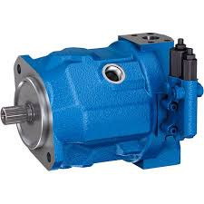
The inner curve motor is a low-speed high-torque hydraulic motor, which is mainly composed of a stator, a rotor, a plunger, a roller set, a distribution shaft, an output shaft and an end cover, and the inner side of the stator is composed of a plurality of curved surfaces having exactly the same shape. The stator acts both as a housing for the motor and as a curved surface of the roller for supporting the roller set for torque transmission.
The internal curve hydraulic motor has a series of characteristics such as small size, light weight, large transmission torque, large shift range, high starting efficiency and low speed stability. It has been obtained in mining machinery, engineering machinery, lifting and transportation machinery, engineering ship machinery. A wide range of applications. In order to detect the output torque of the internal curve hydraulic motor, and thus to monitor and control the operating state of the transmission system, it is usually necessary to install a torque sensor between the internal curve hydraulic motor and the load.
Torque measurement technology
Torque sensors are commonly used to measure the torque of the drive shaft. There are many types of torque sensors. From a mechanical point of view, there are two types of contact torque sensors and non-contact torque sensors.
The torque sensor can be divided into two parts: a signal generating part and a signal receiving part. The signal generating component of the sensor is required to be mounted on the drive shaft and rotate with the drive shaft; and the signal receiving component is required to be stationary and mounted to the frame.
There are many types of contact torque sensors, the most representative of which is the resistance strain gauge torque sensor. The sensor adopts a method in which a resistance strain gauge is attached to the surface of the transmission shaft, and a resistance signal is obtained by deformation of the strain gauge, and then analyzed. It is mainly composed of a strain bridge, a conductive slip ring, a brush and the like.
Due to the pasting method, the adhesive ages and falls off for a long time, which affects the measurement accuracy, and the conductive slip ring is easy to wear, which affects the transmission effect. These sensors are often used in static and low speed conditions up to 500r/min. Non-contact torque sensors are mainly inductive, grating, and magnetoelastic.
Among them, the inductive torque sensor is widely used, and it is mainly composed of a toothed disc, a magnetic steel, a signal coil, a stepping motor and the like. However, due to the characteristics of the magnetoelectric component itself, when the temperature of the working environment changes or is disturbed by an external magnetic field, the magnetoelectric sensor is affected by mechanical shock and vibration, and the sensitivity will change to cause measurement error.
Design
The torque self-test internal curve hydraulic motor is designed to use the Newton's third law, the force and reaction force principle, to measure the torque acting on the motor stator, and then to determine the torque on the motor output shaft.
In view of the fact that the motor stator acts both as the housing of the motor and as the curved surface of the roller, in order to measure the torque of the stator, first, the stator must be in a rotatable state, that is, the stator is separated from the housing, and a groove is provided outside the stator. Supporting the stator with 5 steel balls; secondly, a cantilever is arranged outside the stator, the cantilever extends into the casing, and a piezoelectric ceramic sensor is installed between the cantilever and the casing; third, the output of the piezoelectric ceramic sensor The terminal is connected to a charge amplifier and a signal processor to process the measurement signal.
in conclusion
Torque self-test internal curve hydraulic motor, using Newton's third law, by measuring the torque of the stator, and then calculating the torque of the output shaft, integrating the power transmission and torque measurement, has a simple structure, reliable operation, and is less affected by environmental factors. And so on, can greatly improve the accuracy and efficiency of torque measurement.
Related Products
