Research on Hydraulic Pump Control Technology
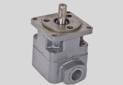
1 blade control technology
The high-pressure energy-saving hydraulic vane pump controls the vane through the electric signal and the pilot hydraulic oil, and uses the solenoid valve to control the pilot oil to pass through the rear distribution disc, leads to the outside of the propeller shaft, and finally flows into the vane pump rotor, the pump shaft, and the vane locking mechanism. The pilot hydraulic oil acts on the slide valve to press a small steel ball into the concave surface of the blade. The blade is completely locked in the blade groove of the rotor, and the sealing volume cannot be formed between the blade, the stator, the rotor and the oil distribution plate, and the blade card The pump is idling, thus stopping the vane pump oil supply cycle, reducing the drive or engine output power, and saving energy.
The high pressure energy-saving vane pump is stuck in the rotor when the system does not require flow and pressure. When the system requires flow and pressure, the blades are released from the stuck position, the blades release the pump oil, and the high-pressure energy-saving vane pump continuously and stably provides the oil with a certain flow and pressure for the working cycle. The transition time for blade sticking and release is completed in 0.2 s. That is to say, when the pump shaft and the rotor are idling, the oil does not circulate, reducing energy loss and achieving energy saving effect. However, the blade locking mechanism makes the blade pump rotor structure more complicated.
Compared with the 25VQ-21 pump of the same rated pressure and flow rate, the 25VQ-21 consumes 2.29 kW of power at no load, while the high-pressure energy-saving vane pump only consumes 0. 25 kW power, calculated by 80% dead time when the system is working, saving ( 2. 29 - 0. 25) × 80% = 1. 632 kW per hour, and the energy saving effect is very good.
2 plunger blade combined with daughter blade
Both the plunger vane pump and the sub-blade pump have their advantages and disadvantages. The sub-mother vane pump has high reliability under most working conditions, but is prone to failure under high speed and high pressure. The plunger vane pump performs well under high speed and high pressure, but the blade is difficult to control at low speed and low output pressure, which easily damages the hydraulic pump. The combination of the plunger blade and the daughter-mother blade can avoid the disadvantages of both and exert the advantages of both.
Reasonable control of the pressure of the inner surface of the stator at different stages can better avoid the wear failure of the stator, so that the working pressure of the vane pump can be greatly improved.
3 two-and-a-half rotor structure
The high-pressure energy-saving vane pump needs to open the oil groove in the rotor and install other control elements such as the valve core. In order to facilitate the machining of the internal oil sump and the installation of the valve plug, the rotor is designed as an axial two-and-a-half rotor structure. After machining the oil grooves inside the two halves of the rotor separately, put the components such as the valve core, and then connect the two halves of the rotor together by means of locating pins and welding.
The welding method is used to connect the two halves of the rotor. The welding method is particularly critical because it generates a large amount of heat during welding. The rotor tends to cause deformation and stress concentration at high temperatures, and also changes the properties of the rotor material.
For components such as the valve core inside the rotor, the thermal deformation will cause the valve hole to be misaligned, and it is impossible to ensure normal and reliable operation after the two halves of the rotor are connected. In the development of high-pressure energy-saving vane pump, the two-half rotor joint is positioned by two positioning cylindrical pins, which effectively prevents the two halves of the rotor from being staggered in the circumferential direction and then connected by laser spot welding. This prevents high temperature deformation of the rotor and valve core, reliable coupling and accurate positioning. The specific approach is as follows:
1 Machining the two halves of the rotor separately for positioning holes; 2 Grinding the abutting surface to remove the burrs; 3 Positioning and clamping the two halves of the rotor with cylindrical pins and clamps; 4 Processing the welding grooves on the outer circular surface; 5 Cleaning the welds To remove dirt such as oil and moisture; 6 Fill in the solder and laser spot weld the two rotors.
4 three-in-one built-in valve technology
The three-in-one built-in valve integrates the relief valve, the phasing valve and the outlet throttle valve into one valve body and is placed in the pump body to control the blades. The relief valve is used to control the oil pressure introduced into the sub-blade chamber and the plunger chamber to regulate and stabilize the pressure.
The phasing valve is used when the system does not need to supply oil, first release the suction pressure, and then lock the blade. When the system needs to be restarted, the blade is released first, and then pressurized by the directional valve, so that the pump is started and closed. The work is smooth and there is no impact between the blades and the stator, thus extending the life of the pump. The outlet throttle valve is used to adjust the pump outlet flow to allow a portion of the flow to flow back.
Related Products
