Optimization Research on Blade Pump Slider Wear Problem
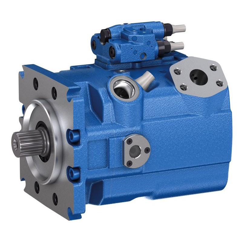
This paper optimizes the blade wear problem of a vane pump. The vane pump uses the blade and the slider, the positioning ring and the inner rotor core to realize the pumping and draining function of the vane. Because the vane and the slider are in direct contact with the rotary motion, Focusing on the maximum eccentricity position and minimum eccentricity position of the blade, the IS-DYNA software is used to analyze the motion of the model. At the same time, considering the rotation of the blade, the inner rotor and the positioning ring will be impacted, and the blade will be forced to vibrate. The blade is worn out against the slider, so the inner rotor and the slider structure are optimized.
The oil pump is the heart of the engine lubrication system. The oil pump draws oil from the oil sump and continuously supplies pressure lubricant to the various friction components of the entire engine. If the oil supply of the oil pump is insufficient, the engine will lack sufficient lubrication pressure, causing severe engine wear. However, if the fuel supply is kept at a very high level, it will inevitably increase the internal loss of the engine and cause unnecessary waste.
Therefore, it is necessary to provide the oil pump to supply the oil according to the demand of the engine. Therefore, with the development of technology, the oil pump provided by the actual demand of the engine for oil pressure is a variable oil pump, and the variable machine The representative product of the oil pump is the vane pump. The advantage is low cost and relatively simple structure. It can ensure the reliable operation of the engine according to the actual working requirements of the engine.
Slider structure optimization
The thickness of the oil absorption area and the oil discharge area is increased by 1.1mm. Considering that the position requires double-sided oil intake, the trade-offs and disadvantages increase the position to 1.1mm, which is the limit position, thus reducing the peak force of the blade movement to the position and ensuring the blade operation. Smooth, at the same time in the oil inlet area, the slider increases the two-way chamfer, which is beneficial to the oil suction chamber on both sides.
Inner rotor structure optimization
The inner rotor is directly driven by the crankshaft, and the crankshaft must have crankshaft runout. The crankshaft runout of this model is 0.03, and the clearance between the crankshaft and the inner rotor is 0.25. This causes the inner rotor to generate a large excitation shock with the crankshaft's runout and drive clearance. In turn, an excitation shock is generated between the blade and the slider, which is also a factor causing the wear of the slider. After the inner rotor is added to the stop, the crankshaft is driven by the inner rotor and is not affected by the crankshaft jump and the drive tolerance, and will be along the inner The rotation center of the rotor rotates, which greatly reduces the excitation shock of the inner rotor to the blade, thereby making the rotation of the blade smooth and avoiding the wear of the slider.
in conclusion
Through optimization of the above schemes, the engine was subjected to two rounds of 400h endurance test, and no slider wear problem occurred. The optimization scheme was effectively verified. The following figure shows the photos after the endurance test, and the slider wear condition is intact.
Related Products
